Introduction to Eagle and Gerber Formats
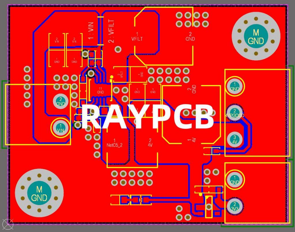
Eagle (Easily Applicable Graphical Layout Editor) is a popular PCB (Printed Circuit Board) design software used by electronic engineers and hobbyists. It allows users to create schematic diagrams and PCB Layouts for their electronic projects. Once the PCB design is complete, it needs to be converted into a format that can be understood by PCB manufacturers. This is where Gerber files come into play.
Gerber format, also known as RS-274X, is a standard file format used in the PCB industry to describe the printed circuit board images. It is a vector image file format that contains information about the copper layers, solder mask, silkscreen, and drill holes of a PCB. Gerber files are essential for PCB Fabrication as they provide the necessary data to manufacture the physical board.
In this article, we will guide you through the process of converting your Eagle PCB design files into Gerber format, making them ready for PCB manufacturing.
Prerequisites
Before we dive into the conversion process, ensure that you have the following:
- Eagle software installed on your computer
- A completed PCB design in Eagle
- Basic understanding of Eagle’s user interface and features

Step-by-Step Guide to Convert Eagle to Gerber
Step 1: Open Your Eagle PCB Design
Launch the Eagle software on your computer and open the PCB design project that you want to convert to Gerber format. Make sure that your design is complete and error-free before proceeding with the conversion process.
Step 2: Run the CAM Processor
In Eagle, the CAM (Computer Aided Manufacturing) Processor is responsible for generating the Gerber files. To access the CAM Processor, follow these steps:
- Click on the “File” menu in the top menu bar.
- Select “CAM Processor” from the dropdown menu.
The CAM Processor window will open, displaying various tabs and settings.
Step 3: Select the Gerber Device
In the CAM Processor window, you need to select the appropriate Gerber device. The Gerber device determines the output format and settings for the generated Gerber files. To select the Gerber device:
- Click on the “Device” dropdown menu in the CAM Processor window.
- Choose “GERBER_RS274X” from the list of available devices.
Step 4: Configure the Gerber Job
Next, you need to configure the Gerber job to specify which layers and files you want to include in the Gerber output. Follow these steps:
- In the CAM Processor window, click on the “File” menu and select “Open” > “Job”.
- Navigate to the Eagle installation directory and open the “cam” folder.
- Select the “gerber.cam” job file and click “Open”.
The gerber.cam job file contains predefined settings for generating standard Gerber files.
Step 5: Customize the Gerber Job (Optional)
If you need to customize the Gerber job to include specific layers or adjust settings, you can do so in the CAM Processor window. Here are a few common customizations:
- Layers: You can select which layers to include in the Gerber output by checking or unchecking the corresponding checkboxes in the “Layer” column.
- Drill Files: To generate drill files, make sure the “Drill Unplated” and “Drill Plated” options are selected in the “Drill” tab.
- Apertures: Review the aperture settings in the “Aperture” tab to ensure they match your PCB manufacturer’s requirements.
Step 6: Generate Gerber Files
Once you have configured the Gerber job, you are ready to generate the Gerber files. Follow these steps:
- In the CAM Processor window, click on the “Process Job” button.
- Choose a destination folder where you want to save the generated Gerber files.
- Click “OK” to start the Gerber File Generation process.
Eagle will now create the Gerber files based on your selected settings. The generated files will be saved in the specified destination folder.
Step 7: Verify and Inspect Gerber Files
After generating the Gerber files, it is crucial to verify and inspect them to ensure they are accurate and complete. Here are a few ways to check your Gerber files:
- Visual Inspection: Open the generated Gerber files in a Gerber Viewer software or online viewer. Visually inspect each layer to check for any errors, missing features, or incorrect dimensions.
- Automated Verification: Use a Gerber file verification tool or service provided by your PCB manufacturer to automatically check for common errors and issues.
- Compare with PCB Design: Cross-reference the generated Gerber files with your original Eagle PCB design to ensure all the layers and features are accurately represented.

Tips and Best Practices
To ensure a smooth conversion process and high-quality Gerber files, consider the following tips and best practices:
- Keep your PCB design clean and organized: Use proper naming conventions, keep your layers organized, and avoid overlapping or conflicting elements in your design.
- Follow your PCB manufacturer’s guidelines: Consult with your PCB manufacturer for their specific Gerber file requirements, such as file naming conventions, layer specifications, and aperture settings.
- Use the latest version of Eagle: Make sure you are using the most up-to-date version of Eagle to take advantage of the latest features and bug fixes.
- Double-check your settings: Before generating the Gerber files, review your settings in the CAM Processor to avoid any unintended changes or omissions.
- Communicate with your PCB manufacturer: If you have any doubts or questions about the Gerber file requirements, reach out to your PCB manufacturer for clarification and guidance.

Frequently Asked Questions (FAQ)
- What are Gerber files, and why are they important?
Gerber files are standard file formats used in the PCB industry to describe the printed circuit board images. They contain information about the copper layers, solder mask, silkscreen, and drill holes of a PCB. Gerber files are essential for PCB fabrication as they provide the necessary data to manufacture the physical board. - Can I use other PCB design software besides Eagle to generate Gerber files?
Yes, most PCB design software packages have the capability to generate Gerber files. The specific steps and settings may vary depending on the software you are using, but the general process is similar to what we described for Eagle. - What should I do if my PCB manufacturer requires specific Gerber file settings?
If your PCB manufacturer has specific requirements for Gerber files, such as file naming conventions or layer specifications, make sure to follow their guidelines. Consult with their technical support or documentation to ensure you are providing the necessary files and settings. - How can I verify the accuracy of my generated Gerber files?
You can visually inspect the generated Gerber files using a Gerber viewer software or online viewer to check for any errors or discrepancies. Additionally, many PCB manufacturers provide automated verification tools or services to check for common issues in Gerber files. - What are some common mistakes to avoid when generating Gerber files?
Some common mistakes to avoid include: not selecting the correct layers, using incorrect file naming conventions, forgetting to include drill files, and not following the PCB manufacturer’s guidelines. Double-check your settings and files before submitting them for fabrication.
Conclusion
Converting your Eagle PCB design to Gerber format is a crucial step in the PCB manufacturing process. By following the step-by-step guide provided in this article, you can easily generate Gerber files that are ready for fabrication. Remember to select the appropriate Gerber device, configure the Gerber job settings, and verify the generated files for accuracy.
By understanding the importance of Gerber files and adhering to best practices, you can ensure a smooth and successful PCB manufacturing experience. Don’t hesitate to reach out to your PCB manufacturer for any specific requirements or guidance.
With your Eagle PCB design converted to Gerber format, you are one step closer to bringing your electronic project to life. Happy PCB designing and manufacturing!

No responses yet