What is Rigid-Flex PCB Design?
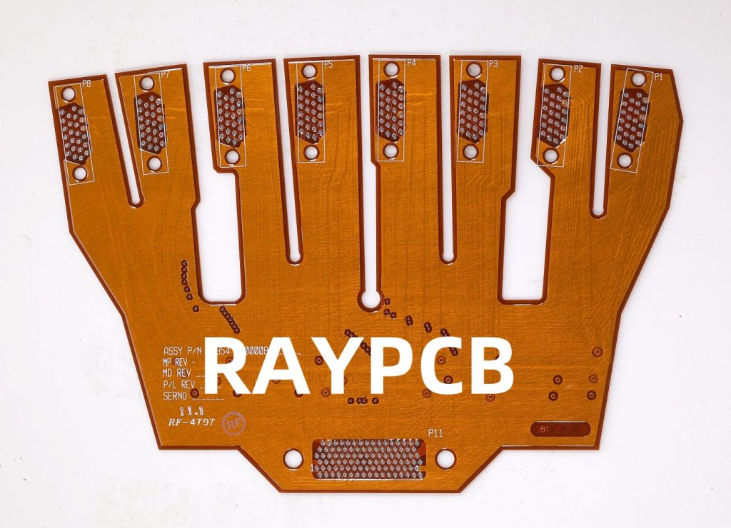
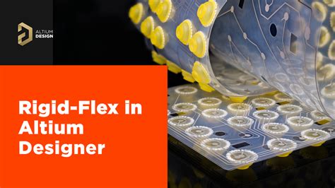
Rigid-flex PCB design is a type of printed circuit board that combines both rigid and flexible substrates into a single, integrated assembly. The rigid portions of the board provide structural support and house the majority of the components, while the flexible portions allow the board to bend and fold, enabling more compact and complex designs.
Advantages of Rigid-Flex PCB Design
- Space Savings: Rigid-flex PCBs can be folded and bent to fit into tight spaces, reducing the overall size of the electronic assembly.
- Increased Reliability: By eliminating the need for connectors and cables between rigid boards, rigid-flex PCBs reduce the risk of connection failures and improve overall system reliability.
- Improved Signal Integrity: The integrated nature of rigid-flex PCBs minimizes signal loss and interference, resulting in better signal integrity compared to traditional multi-board assemblies.
- Enhanced Durability: Rigid-flex PCBs are more resistant to vibration and shock, making them ideal for applications in harsh environments.
Material Selection for Rigid-Flex PCB Design
Choosing the right materials is crucial for the success of a rigid-flex PCB design. The most common materials used in rigid-flex PCBs are:
Flexible Substrate Materials
- Polyimide (PI): Polyimide is the most widely used flexible substrate material due to its excellent thermal stability, chemical resistance, and mechanical strength.
- Polyethylene Terephthalate (PET): PET is a lower-cost alternative to polyimide, offering good flexibility and electrical properties, but with reduced thermal stability.
Rigid Substrate Materials
- FR-4: FR-4 is a glass-reinforced epoxy laminate that is commonly used for the rigid portions of rigid-flex PCBs. It offers good mechanical strength and electrical insulation properties.
- High-Frequency Laminates: For applications requiring higher frequency operation, specialized laminates such as Rogers or Isola materials may be used to minimize signal loss and maintain signal integrity.
Adhesives
Adhesives are used to bond the flexible and rigid portions of the PCB together. The most common adhesives used in rigid-flex PCB design are:
- Acrylic: Acrylic adhesives offer good bonding strength and flexibility, making them suitable for most rigid-flex applications.
- Epoxy: Epoxy adhesives provide higher strength and temperature resistance compared to acrylic adhesives, but may be more brittle.

Layout Considerations for Rigid-Flex PCB Design
Proper layout is essential for ensuring the reliability and performance of a rigid-flex PCB. Some key considerations include:
Bend Radius
The bend radius is the minimum radius at which the flexible portion of the PCB can be bent without causing damage. It is important to design the flexible portions with a sufficient bend radius to prevent stress on the copper traces and ensure long-term reliability.
| Material | Minimum Bend Radius |
|---|---|
| Polyimide | 6x material thickness |
| PET | 8x material thickness |
Copper Thickness
The copper thickness on the flexible portions of the PCB should be minimized to reduce stress during bending. A typical copper thickness for flexible regions is 1/2 oz or less.
Coverlay
A coverlay is a protective layer that is applied over the flexible portions of the PCB to prevent damage and provide electrical insulation. The coverlay should be designed with sufficient overlap onto the rigid portions to ensure a secure bond.
Stiffeners
Stiffeners are used to provide additional support and rigidity to the flexible portions of the PCB, particularly in areas where components are mounted. Stiffeners can be made from a variety of materials, such as FR-4, polyimide, or metal.

Manufacturing Processes for Rigid-Flex PCB Design
The manufacturing process for rigid-flex PCBs is more complex than that of traditional rigid PCBs, and requires specialized equipment and expertise. The key steps in the manufacturing process include:
- Flexible Substrate Preparation: The flexible substrate material is cut to size and shape, and any necessary openings or features are created.
- Rigid Substrate Preparation: The rigid substrate material is cut to size and shape, and any necessary openings or features are created.
- Lamination: The flexible and rigid substrates are laminated together using adhesives and pressure.
- Drilling: Holes are drilled through the rigid and flexible portions of the PCB as required for component mounting and interconnections.
- Plating: Copper is plated onto the drilled holes and any other exposed copper surfaces to provide electrical connectivity.
- Etching: Unwanted copper is etched away to create the desired circuit patterns.
- Coverlay Application: The coverlay is applied over the flexible portions of the PCB and bonded using heat and pressure.
- Surface Finish: A surface finish, such as HASL or ENIG, is applied to protect the exposed copper and provide a solderable surface for component assembly.

Best Practices for Rigid-Flex PCB Design
To ensure the success of a rigid-flex PCB design, consider the following best practices:
- Collaborate with your PCB manufacturer early in the design process to ensure that your design is manufacturable and to optimize the layout for cost and reliability.
- Use 3D modeling tools to visualize the final assembly and ensure that the flexible portions of the PCB can be bent and folded as required without causing stress or interference.
- Follow the manufacturer’s guidelines for minimum bend radius, copper thickness, and coverlay design to ensure long-term reliability.
- Use stiffeners strategically to provide support for components and to control the bending of the flexible portions of the PCB.
- Consider the use of strain relief features, such as slots or cut-outs, to reduce stress on the flexible portions of the PCB during bending.
- Plan for the assembly process, including the order in which components will be mounted and the methods used for soldering and inspection.
Frequently Asked Questions (FAQ)
1. What is the difference between rigid-flex and flex PCBs?
Rigid-flex PCBs combine both rigid and flexible substrates into a single, integrated assembly, while flex PCBs are made entirely from flexible materials. Rigid-flex PCBs offer the advantages of both rigidity and flexibility, while flex PCBs are typically used for applications requiring high flexibility and low weight.
2. Can rigid-flex PCBs be used for high-frequency applications?
Yes, rigid-flex PCBs can be designed for high-frequency applications by using specialized substrate materials, such as Rogers or Isola laminates, and by following best practices for signal integrity, such as minimizing signal path lengths and using controlled impedance design techniques.
3. How do I select the right adhesive for my rigid-flex PCB design?
The choice of adhesive depends on the specific requirements of your application, including the operating temperature range, the level of flexibility required, and the environmental conditions that the PCB will be exposed to. Consult with your PCB manufacturer to select the best adhesive for your design.
4. What is the typical turnaround time for a rigid-flex PCB Prototype?
The turnaround time for a rigid-flex PCB prototype can vary depending on the complexity of the design and the workload of the manufacturer. Typical turnaround times range from 2-3 weeks for simple designs to 4-6 weeks for more complex designs.
5. How can I reduce the cost of my rigid-flex PCB design?
To reduce the cost of your rigid-flex PCB design, consider the following strategies:
– Minimize the number of layers and the overall size of the PCB.
– Use standard materials and processes wherever possible.
– Optimize the layout to minimize the amount of flexible material required.
– Work closely with your PCB manufacturer to identify cost-saving opportunities in the design and manufacturing process.
Conclusion
Rigid-flex PCB design offers a powerful solution for creating compact, reliable, and high-performance electronic assemblies. By following best practices for material selection, layout, and manufacturing, designers can create rigid-flex PCBs that meet the unique requirements of their applications while minimizing cost and risk. As the demand for smaller, more complex electronic devices continues to grow, rigid-flex PCB design will play an increasingly important role in enabling the next generation of innovative products.

No responses yet