Introduction to Rigid-Flex PCB
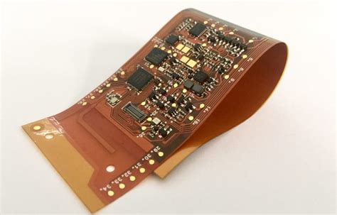
Rigid-Flex PCB is a type of printed circuit board that combines both rigid and flexible substrates into a single board. This unique design allows for greater flexibility and durability compared to traditional rigid or Flexible PCBs. Rigid-Flex PCBs are widely used in various electronic projects, from consumer electronics to aerospace applications.
What is a Rigid-Flex PCB?
A Rigid-Flex PCB consists of multiple layers of flexible and rigid substrates laminated together. The flexible layers are typically made of polyimide or other flexible materials, while the rigid layers are made of standard FR-4 or other rigid materials. The layers are interconnected using plated through-holes (PTHs) or other methods, allowing for electrical connectivity between the layers.
Advantages of Rigid-Flex PCBs
- Space savings: Rigid-Flex PCBs allow for more compact designs by eliminating the need for connectors and cables between rigid and flexible sections.
- Improved reliability: By reducing the number of interconnects, Rigid-Flex PCBs minimize potential points of failure, resulting in higher reliability.
- Enhanced flexibility: The flexible sections of Rigid-Flex PCBs enable the board to bend and fold, making it ideal for applications with limited space or unusual form factors.
- Reduced weight: Rigid-Flex PCBs are generally lighter than equivalent designs using separate rigid and flexible boards connected by cables or connectors.
- Simplified assembly: With fewer components to assemble, Rigid-Flex PCBs can simplify the manufacturing process and reduce assembly time.
Rigid-Flex PCB vs. Flexible PCB
While both Rigid-Flex PCBs and Flexible PCBs offer the benefit of flexibility, there are several key differences between the two:
| Feature | Rigid-Flex PCB | Flexible PCB |
|---|---|---|
| Substrate | Combination of rigid and flexible materials | Flexible materials only |
| Rigidity | Rigid sections provide structural support | No rigid sections |
| Durability | More durable due to rigid sections | Less durable, prone to tearing or damage |
| Applications | Suitable for applications requiring both flexibility and structural support | Suitable for applications requiring flexibility only |
| Cost | Higher cost due to complex manufacturing process | Lower cost compared to Rigid-Flex PCBs |
When to use Rigid-Flex PCBs
Rigid-Flex PCBs are ideal for applications that require:
- Compact designs with limited space
- High reliability and durability
- Unusual form factors or shapes
- Reduced weight
- Simplified assembly
Some common applications of Rigid-Flex PCBs include:
- Wearable devices
- Medical devices
- Aerospace and military equipment
- Automotive electronics
- Consumer electronics

Designing Rigid-Flex PCBs
Designing Rigid-Flex PCBs requires careful consideration of several factors to ensure optimal performance and manufacturability.
Bend radius and flexibility
One of the most critical aspects of Rigid-Flex PCB Design is determining the appropriate bend radius and flexibility of the flexible sections. The bend radius should be large enough to prevent damage to the copper traces and substrate during flexing, while still allowing for the desired form factor. The minimum bend radius is typically 6 times the thickness of the flexible layer.
Layer stackup
The layer stackup of a Rigid-Flex PCB must be carefully planned to ensure proper electrical performance and mechanical stability. The rigid and flexible layers should be arranged in a way that minimizes stress on the flexible sections during bending. Additionally, the layer stackup should be optimized for signal integrity, power distribution, and EMI shielding as needed.
Material selection
Choosing the appropriate materials for a Rigid-Flex PCB is crucial for ensuring reliability and performance. The flexible substrate material should have good electrical properties, high tensile strength, and resistance to environmental factors such as temperature and humidity. Common flexible substrate materials include polyimide, polyester, and PTFE. The rigid substrate material should also have good electrical and mechanical properties, with FR-4 being the most common choice.
Interconnect design
The interconnects between the rigid and flexible sections of a Rigid-Flex PCB must be carefully designed to minimize stress and ensure reliable electrical connections. Plated through-holes (PTHs) are the most common method of interconnecting the layers, but other methods such as microvias and blind vias can also be used. The interconnect design should take into account the different coefficients of thermal expansion (CTE) of the rigid and flexible materials to prevent delamination or other damage during temperature cycling.

Manufacturing Rigid-Flex PCBs
Manufacturing Rigid-Flex PCBs is a complex process that requires specialized equipment and expertise.
Fabrication process
The fabrication process for Rigid-Flex PCBs typically involves the following steps:
- Patterning the copper layers on the flexible and rigid substrates
- Laminating the flexible and rigid layers together
- Drilling and plating the interconnect holes
- Applying solder mask and silkscreen
- Cutting and profiling the board to the desired shape
Challenges in manufacturing
Manufacturing Rigid-Flex PCBs presents several challenges compared to traditional rigid or flexible PCBs:
- Accurate alignment of the flexible and rigid layers during lamination
- Ensuring proper adhesion between the layers to prevent delamination
- Maintaining the desired bend radius and flexibility during profiling
- Minimizing stress on the interconnects during assembly and use
To overcome these challenges, manufacturers use specialized equipment and processes, such as:
- Precision alignment systems for layer registration
- Controlled-depth milling for selective removal of rigid layers
- Laser cutting for precise profiling of the board shape
- Specialized lamination presses for bonding the layers together
Testing and Quality Control
Ensuring the quality and reliability of Rigid-Flex PCBs requires rigorous testing and quality control measures.
Electrical testing
Electrical testing of Rigid-Flex PCBs includes:
- Continuity Testing to verify proper electrical connections between layers
- Insulation resistance testing to ensure adequate insulation between conductors
- High-potential (HiPot) testing to detect any breakdown in insulation
- Impedance testing to verify the characteristic impedance of controlled-impedance traces
Mechanical testing
Mechanical testing of Rigid-Flex PCBs includes:
- Bend testing to ensure the board can withstand the required number of flex cycles without damage
- Peel strength testing to verify adequate adhesion between layers
- Thermal cycling testing to ensure the board can withstand temperature fluctuations without delamination or other damage
Visual inspection
Visual inspection of Rigid-Flex PCBs is critical for detecting any defects or anomalies that may affect performance or reliability. This includes:
- Checking for proper layer alignment and registration
- Inspecting for any signs of delamination or damage to the substrates
- Verifying the correct placement and size of holes and vias
- Checking for any defects in the solder mask or silkscreen
By implementing comprehensive testing and quality control measures, manufacturers can ensure that Rigid-Flex PCBs meet the required specifications and perform reliably in their intended applications.
Frequently Asked Questions (FAQ)
- What is the difference between Rigid-Flex PCBs and Flexible PCBs?
- Rigid-Flex PCBs combine both rigid and flexible substrates into a single board, while Flexible PCBs consist of flexible substrates only. Rigid-Flex PCBs offer the benefits of both rigidity and flexibility, while Flexible PCBs provide flexibility only.
- What are the advantages of using Rigid-Flex PCBs in electronic projects?
- Rigid-Flex PCBs offer several advantages, including space savings, improved reliability, enhanced flexibility, reduced weight, and simplified assembly. These benefits make Rigid-Flex PCBs ideal for applications with limited space, unusual form factors, or high reliability requirements.
- How do you determine the appropriate bend radius for a Rigid-Flex PCB?
- The minimum bend radius for a Rigid-Flex PCB is typically 6 times the thickness of the flexible layer. However, the actual bend radius should be determined based on the specific design requirements, material properties, and the number of flex cycles expected over the product’s lifetime.
- What materials are commonly used for the flexible layers in Rigid-Flex PCBs?
- Common flexible substrate materials for Rigid-Flex PCBs include polyimide, polyester, and PTFE (Teflon). These materials offer good electrical properties, high tensile strength, and resistance to environmental factors such as temperature and humidity.
- What are some of the challenges in manufacturing Rigid-Flex PCBs?
- Manufacturing Rigid-Flex PCBs presents several challenges, including accurate alignment of the flexible and rigid layers during lamination, ensuring proper adhesion between the layers to prevent delamination, maintaining the desired bend radius and flexibility during profiling, and minimizing stress on the interconnects during assembly and use. Specialized equipment and processes are used to overcome these challenges and ensure high-quality, reliable Rigid-Flex PCBs.
Conclusion
Rigid-Flex PCBs offer a unique combination of rigidity and flexibility that makes them ideal for a wide range of electronic projects. By combining the benefits of both rigid and flexible substrates into a single board, Rigid-Flex PCBs enable more compact, reliable, and versatile designs compared to traditional rigid or flexible PCBs.
Designing and manufacturing Rigid-Flex PCBs requires careful consideration of several factors, including bend radius, layer stackup, material selection, and interconnect design. Specialized equipment and processes are used to overcome the challenges associated with manufacturing Rigid-Flex PCBs and ensure high-quality, reliable boards.
As electronic devices continue to become smaller, more complex, and more versatile, the demand for Rigid-Flex PCBs is expected to grow. By understanding the benefits, design considerations, and manufacturing processes associated with Rigid-Flex PCBs, engineers and designers can leverage this technology to create innovative and reliable electronic products that meet the evolving needs of their customers.
No responses yet