Introduction to Polyimide PCBs
Polyimide PCBs are a type of printed circuit board (PCB) that use polyimide as the base material instead of the more common FR-4 (flame retardant-4) material. Polyimide is a high-performance polymer known for its exceptional thermal stability, chemical resistance, and mechanical strength. These properties make polyimide PCBs an ideal choice for applications that require reliability under harsh environmental conditions, such as in aerospace, military, and high-temperature electronics.
Polyimide PCBs come in two main varieties: rigid and flexible. Rigid polyimide PCBs are similar to traditional FR-4 boards in terms of their rigidity but offer superior performance in demanding environments. Flexible polyimide PCBs, also known as flex PCBs, are designed to bend and flex, making them suitable for applications where conformity to irregular shapes or movement is required.
Advantages of Polyimide PCBs
Polyimide PCBs offer several advantages over traditional FR-4 PCBs:
-
High-Temperature Resistance: Polyimide can withstand temperatures up to 260°C (500°F) continuously and 400°C (752°F) for short durations, making it suitable for high-temperature applications.
-
Excellent Chemical Resistance: Polyimide is resistant to most chemicals, solvents, and oils, ensuring the PCB’s integrity in harsh chemical environments.
-
Superior Mechanical Properties: Polyimide has high tensile strength, low thermal expansion, and good dimensional stability, which contribute to the overall reliability of the PCB.
-
Low Dielectric Constant: Polyimide has a lower dielectric constant compared to FR-4, which results in lower signal loss and better high-frequency performance.
-
Flexibility (for flex PCBs): Flexible polyimide PCBs can bend and flex without damaging the circuit, allowing for more design freedom and use in applications where conformity is required.

Rigid Polyimide PCBs
Rigid polyimide PCBs are constructed using a polyimide laminate material as the base substrate. The laminate is typically composed of multiple layers of polyimide film bonded together with a high-temperature adhesive. Copper Foil is then laminated onto the polyimide substrate to create the conductive layer for circuit traces.
The manufacturing process for rigid polyimide PCBs is similar to that of FR-4 PCBs, involving the following steps:
- Cutting the polyimide laminate to the desired size
- Drilling holes for vias and component mounting
- Plating the holes with copper
- Patterning the copper layer to create circuit traces
- Applying solder mask and silkscreen
- Surface finishing (e.g., ENIG, HASL, or OSP)
Rigid polyimide PCBs are used in various high-reliability applications, such as:
- Aerospace and Military Electronics
- High-temperature sensors and control systems
- Downhole drilling equipment
- Automotive under-hood electronics
- Power electronics and LED lighting

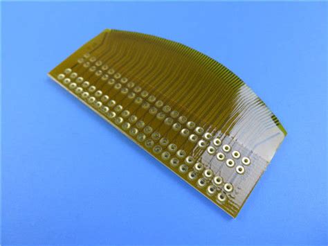
Flexible Polyimide PCBs
Flexible polyimide PCBs, or flex PCBs, are manufactured using a thin, flexible polyimide film as the base material. The most common type of polyimide film used in flex PCBs is DuPont’s Kapton. Copper foil is laminated onto the polyimide film using a high-temperature adhesive, and the circuit traces are formed through a process called photolithography.
Flex PCBs can be categorized into three main types:
- Single-sided flex PCBs: Copper traces are present on only one side of the polyimide film.
- Double-sided flex PCBs: Copper traces are present on both sides of the polyimide film, with plated through-holes connecting the two layers.
- Multi-layer flex PCBs: Multiple layers of polyimide film and copper foil are laminated together, with plated through-holes connecting the layers.
The manufacturing process for flex PCBs involves the following steps:
- Laminating copper foil onto the polyimide film
- Applying a photoresist layer and exposing it to a circuit pattern
- Developing the photoresist and etching away the unwanted copper
- Stripping the remaining photoresist
- Applying a coverlay or soldermask for insulation and protection
- Cutting the flex PCB to the desired shape
Flex PCBs are used in applications that require flexibility, such as:
- Wearable electronics
- Medical devices
- Aerospace and military equipment
- Consumer electronics (e.g., smartphones, laptops)
- Automotive electronics (e.g., dashboard displays, sensors)

Polyimide Laminate Materials
Polyimide laminates are the foundation of both rigid and flex polyimide PCBs. These laminates are composed of polyimide films bonded together with high-temperature adhesives and coated with copper foil. The most common polyimide film used in the industry is DuPont’s Kapton, which is available in various grades and thicknesses.
Some of the key properties of polyimide laminates include:
- High Glass Transition Temperature (Tg): Polyimide has a Tg of 360°C (680°F), allowing it to maintain its mechanical properties at high temperatures.
- Low coefficient of thermal expansion (CTE): Polyimide has a CTE of 20 ppm/°C, which is much lower than FR-4 (70 ppm/°C), resulting in better dimensional stability.
- High dielectric strength: Polyimide can withstand high voltages without breaking down, making it suitable for high-voltage applications.
- Excellent tear and tensile strength: Polyimide has high mechanical strength, which helps prevent damage during the manufacturing process and in the field.
Common Polyimide Laminate Materials
| Material | Description | Typical Applications |
|---|---|---|
| Kapton HN | General-purpose polyimide film | Rigid and flex PCBs, insulation, and tapes |
| Kapton FN | Polyimide film with low coefficient of friction | Flexible cables and circuits |
| Kapton FPC | Polyimide film with enhanced dimensional stability | High-density interconnects and flex PCBs |
| Kapton MT | Polyimide film with improved adhesion to metal surfaces | Flexible heaters and sensors |
| Pyralux AP | All-polyimide laminate with excellent thermal stability | High-temperature rigid and flex PCBs |
| Pyralux FR | Flame-retardant polyimide laminate | Aerospace and military applications |
Design Considerations for Polyimide PCBs
When designing rigid or flex polyimide PCBs, several factors should be considered to ensure optimal performance and reliability:
-
Thermal Management: Although polyimide can withstand high temperatures, proper thermal management is still essential to prevent overheating and ensure the longevity of components.
-
Dimensional Stability: Polyimide has a low CTE, but designers should still account for potential expansion and contraction during temperature changes.
-
Bend Radius (for flex PCBs): Flex PCBs should be designed with an appropriate bend radius to prevent damage to the copper traces and polyimide film.
-
Adhesion: Proper adhesion between the polyimide film, copper foil, and any additional layers is crucial for the PCB’s reliability.
-
Connector Selection: Choose connectors that are compatible with the polyimide material and can withstand the intended environmental conditions.
-
Manufacturing Capabilities: Consult with the PCB manufacturer to ensure they have experience working with polyimide materials and can meet the required specifications.
Frequently Asked Questions (FAQ)
-
Q: What is the difference between rigid and flex polyimide PCBs?
A: Rigid polyimide PCBs use a polyimide laminate as the base material, resulting in a rigid board that offers high-temperature resistance and excellent mechanical properties. Flex polyimide PCBs use a thin, flexible polyimide film, allowing the PCB to bend and flex without damaging the circuit. -
Q: Can polyimide PCBs be used in high-temperature applications?
A: Yes, polyimide PCBs are well-suited for high-temperature applications due to their ability to withstand temperatures up to 260°C (500°F) continuously and 400°C (752°F) for short durations. -
Q: Are polyimide PCBs more expensive than traditional FR-4 PCBs?
A: Yes, polyimide PCBs are generally more expensive than FR-4 PCBs due to the higher cost of polyimide materials and the specialized manufacturing processes required. -
Q: What are the most common applications for flex polyimide PCBs?
A: Flex polyimide PCBs are commonly used in applications that require flexibility, such as wearable electronics, medical devices, aerospace and military equipment, consumer electronics, and automotive electronics. -
Q: Can rigid and flex polyimide PCBs be combined in a single design?
A: Yes, Rigid-Flex PCBs combine both rigid and flexible sections, allowing for more complex designs and improved reliability in applications that require both rigidity and flexibility.
Conclusion
Rigid and flex polyimide PCBs offer unique advantages over traditional FR-4 PCBs, particularly in applications that require high-temperature resistance, chemical stability, and mechanical strength. By understanding the properties of polyimide laminate materials and the design considerations for these PCBs, engineers can create reliable and high-performance electronic systems for demanding environments.
As technology continues to advance, the use of polyimide PCBs is expected to grow in various industries, from aerospace and military to consumer electronics and automotive. With their exceptional properties and versatility, polyimide PCBs are poised to play a crucial role in shaping the future of electronic design and manufacturing.
No responses yet