Introduction to Gerber Formats
Gerber format is a standard file format used in the printed circuit board (PCB) industry to describe the printed circuit board images: copper layers, solder mask, legend, drill data, etc. It is a vector image file format plot and is the de facto standard used by PCB industry software to describe the printed circuit board images: copper layers, solder mask, legend, drill data, etc.
History of Gerber Format
The Gerber file format was originally developed by the Gerber Systems Corp., a division of Gerber Scientific, founded by Joseph Gerber. The format is now owned by Ucamco through its acquisition of Barco ETS, a company that previously acquired Gerber Systems Corp.
Types of Gerber Formats
There are three types of Gerber formats:
- Standard Gerber
- Extended Gerber
- Gerber X2
Standard Gerber
The Standard Gerber format, also known as RS-274-D, is a subset of EIA RS-274-D that was standardized as early as the 1960s. It has a limited set of 24 commands (D-codes) that are used to draw tracks and pads.
Extended Gerber
The Extended Gerber format, also known as RS-274X, is an extension of the Standard Gerber format that allows for more advanced features and a wider range of aperture shapes. It was introduced in 1998 and has since become the most widely used format in the PCB industry.
Gerber X2
Gerber X2 is the latest Gerber format, introduced in 2014. It builds on the Extended Gerber format and adds new features such as nested step and repeat and attributes. Gerber X2 files are fully backward compatible with the Extended Gerber format.

Gerber File Structure
A Gerber file consists of a sequence of commands that describe the image. The commands are made up of ASCII characters and are case-sensitive. Each command is terminated by an asterisk (*).
Coordinate Data
Coordinate data is used to specify the position of a point on the PCB. It consists of an X value and a Y value, separated by a comma. For example:
X100Y200*
This specifies a point at X=100 and Y=200.
Aperture Definitions
Apertures are used to draw the features on the PCB. They are defined using the AD command, followed by the aperture number and the aperture type and size. For example:
%ADD10C,0.1*%
This defines aperture number 10 as a circle with a diameter of 0.1 units.
D-Codes
D-codes are used to select the aperture that is currently being used to draw features. They are specified using the Dnn command, where nn is the aperture number. For example:
D10*
This selects aperture number 10 as the current aperture.
Polarity
Polarity is used to specify whether the features being drawn should be additive (dark) or subtractive (clear). It is specified using the %LPD% and %LPC% commands for dark and clear polarity, respectively.
Step and Repeat
Step and repeat is used to duplicate a feature multiple times with a specified offset. It is specified using the SR command, followed by the X and Y offsets and the number of repeats. For example:
%SRX1Y1I5J5*%
This specifies a step and repeat with an X offset of 1, a Y offset of 1, and 5 repeats in both the X and Y directions.

Gerber File Extensions
Gerber files use different file extensions to specify the layer type. The most common file extensions are:
| Extension | Layer Type |
|---|---|
| .GTL | Top copper layer |
| .GBL | Bottom copper layer |
| .GTO | Top silkscreen overlay |
| .GBO | Bottom silkscreen overlay |
| .GTP | Top solder paste |
| .GBP | Bottom solder paste |
| .GTS | Top solder mask |
| .GBS | Bottom solder mask |
| .GM1 | Mechanical layer 1 |
| .GD1 | Drill drawing |
| .GG1 | Fabrication drawing |

Gerber File Creation
Gerber files are typically created using PCB design software such as Altium Designer, KiCad, or Eagle. The software allows the user to design the PCB and then generate the Gerber files for manufacturing.
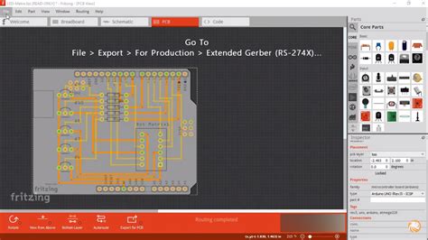
Exporting Gerber Files
To export Gerber files from PCB design software, follow these general steps:
- Open the PCB design in the software.
- Go to the File menu and select “Export” or “Generate Gerber Files”.
- Select the layers to include in the Gerber files.
- Specify the output directory and file format (e.g., RS-274X).
- Click “Export” or “Generate” to create the Gerber files.
Gerber File Verification
After generating the Gerber files, it is important to verify that they are correct and complete. This can be done using a Gerber file viewer such as GC-Prevue or ViewMate.
A Gerber file viewer allows you to visually inspect the PCB Layers and check for any errors or omissions. It is also a good idea to send the Gerber files to the PCB manufacturer for verification before starting production.
FAQ
What is the difference between Standard Gerber and Extended Gerber?
Standard Gerber (RS-274-D) is an older format with limited commands and aperture shapes. Extended Gerber (RS-274X) is a newer format that adds support for more advanced features and a wider range of aperture shapes.
Can Gerber files be edited?
Gerber files are not intended to be edited directly. If changes need to be made to the PCB design, they should be made in the PCB design software and then new Gerber files should be generated.
What is the purpose of a solder mask layer in a Gerber file?
A solder mask layer specifies the areas of the PCB that should be covered with solder mask, which is a protective coating that prevents solder from adhering to the copper traces. Solder mask is typically applied to the top and bottom of the PCB, with openings for the pads and other features that need to be soldered.
How do I know which file extension to use for each layer type?
The file extensions for Gerber files are standardized and specify the layer type. For example, .GTL is used for the top copper layer, .GBL for the bottom copper layer, .GTO for the top silkscreen overlay, etc. The PCB design software will automatically generate the correct file extensions when exporting Gerber files.
Can Gerber files be used for other manufacturing processes besides PCBs?
While Gerber files are primarily used for PCB manufacturing, they can also be used for other applications such as creating stencils for solder paste application or generating artwork for front panels and other mechanical parts. However, the specific requirements for these applications may vary and require additional processing or modification of the Gerber files.
Conclusion
Gerber files are an essential part of the PCB manufacturing process, providing a standardized format for describing the various layers and features of a printed circuit board. By understanding the different types of Gerber formats, file structure, and extensions, PCB designers can ensure that their designs are accurately translated into physical boards.
When creating Gerber files, it is important to use the correct file extensions for each layer type and to verify the files using a Gerber file viewer before sending them to the manufacturer. By following these best practices, designers can minimize errors and delays in the manufacturing process and ensure that their PCBs are produced to the highest quality standards.
No responses yet