Understanding the Basics of PCB Design
What is a PCB?
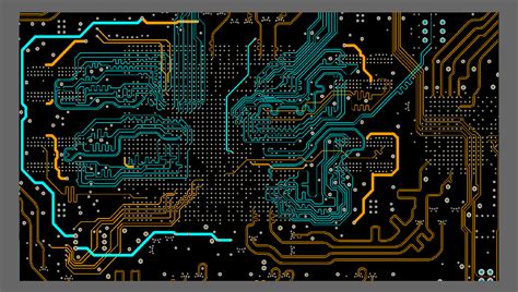
A PCB is a flat board made of insulating material, such as fiberglass or plastic, with conductive copper traces printed on its surface. These traces connect various electronic components, such as resistors, capacitors, and integrated circuits (ICs), to form a complete electronic circuit.
Types of PCBs
There are three main types of PCBs:
- Single-layer PCBs: These have conductive traces on only one side of the board.
- Double-layer PCBs: These have conductive traces on both sides of the board, allowing for more complex circuits and higher component density.
- Multi-layer PCBs: These have multiple layers of conductive traces separated by insulating layers, enabling even more complex circuits and higher component density.
PCB Design Software
To design a PCB, you will need to use specialized software. Some popular PCB design software options include:
- Altium Designer
- KiCad
- Eagle
- OrCAD
- Mentor Graphics PADS
These software tools allow you to create schematic diagrams, design the PCB layout, and generate the necessary files for manufacturing.
Planning Your PCB Design
Define Your Project Requirements
Before starting your PCB design, it is essential to define your project requirements clearly. Consider the following factors:
- The purpose and functionality of the electronic device
- The size and shape constraints of the PCB
- The power requirements and voltage levels
- The environmental conditions (temperature, humidity, vibration, etc.)
- The manufacturing process and budget
Create a Schematic Diagram
A schematic diagram is a graphical representation of the electronic circuit, showing the components and their interconnections. When creating a schematic diagram, follow these best practices:
- Use standard symbols for components
- Label all components and nets clearly
- Use hierarchical design for complex circuits
- Perform a design review to catch any errors or inconsistencies
Component Selection
Choosing the right components is crucial for the success of your PCB design. Consider the following factors when selecting components:
- Functionality and performance requirements
- Availability and lead time
- Cost and budget
- Package size and type
- Thermal characteristics

PCB Layout Design
Component Placement
When placing components on the PCB, consider the following guidelines:
- Group related components together
- Place components to minimize the length of traces
- Consider the thermal requirements of components
- Ensure proper spacing between components for manufacturing and assembly
Routing and Trace Design
Routing is the process of creating the conductive traces that connect the components on the PCB. When designing traces, keep these best practices in mind:
- Use appropriate trace widths based on current requirements
- Minimize trace lengths to reduce signal integrity issues
- Avoid sharp angles and use curved traces instead
- Use ground planes and power planes for better signal integrity and EMI reduction
Grounding and Power Distribution
Proper grounding and power distribution are essential for the performance and reliability of your PCB. Follow these guidelines:
- Use a solid ground plane to provide a low-impedance return path for signals
- Use separate ground planes for analog and digital circuits to reduce noise coupling
- Use decoupling capacitors near ICs to reduce power supply noise
- Use appropriate trace widths for power traces based on current requirements

PCB Manufacturing and Assembly
PCB Fabrication
Once your PCB design is complete, you will need to send the design files to a PCB fabrication house. The most common file formats for PCB fabrication are:
- Gerber files: These are the industry standard for PCB fabrication and include information about the copper layers, solder mask, and silkscreen.
- Drill files: These specify the location and size of the holes on the PCB.
- Fabrication drawings: These provide additional information, such as the board outline, material specifications, and special instructions.
When choosing a PCB fabrication house, consider their reputation, quality control processes, lead times, and pricing.
PCB Assembly
After the PCB is fabricated, it needs to be populated with components. There are two main methods for PCB assembly:
- Through-hole assembly: Components with leads are inserted through holes in the PCB and soldered on the opposite side.
- Surface-mount assembly: Components are placed directly on the surface of the PCB and soldered in place.
When designing your PCB, consider the assembly method and choose components and package types accordingly. Provide clear assembly instructions and bill of materials (BOM) to the assembly house.

Testing and Debugging
Visual Inspection
Before powering up your PCB, perform a thorough visual inspection to check for any manufacturing defects or assembly issues, such as:
- Broken or misaligned traces
- Solder bridges or cold solder joints
- Incorrect component placement or orientation
- Missing or damaged components
Functional Testing
After visual inspection, perform functional testing to verify that the PCB operates as intended. This may include:
- Power-on testing to check for proper voltage levels and current consumption
- Signal integrity testing to ensure proper communication between components
- Environmental testing to validate the PCB’s performance under specified conditions
Debugging and Troubleshooting
If issues are found during testing, use the following techniques to debug and troubleshoot your PCB:
- Use a multimeter to measure voltages and continuity
- Use an oscilloscope to observe signal waveforms and timing
- Use thermal imaging to identify hot spots and thermal issues
- Review the schematic and layout to identify potential design issues
- Consult with experienced engineers or online resources for guidance
Best Practices for PCB Design
Design for Manufacturability (DFM)
To ensure that your PCB can be manufactured reliably and cost-effectively, follow these DFM guidelines:
- Use standard component sizes and package types
- Provide adequate spacing between components and traces
- Avoid using very small trace widths or spacing
- Use vias and test points sparingly
- Follow the fabrication house’s design rules and guidelines
Design for Testability (DFT)
Incorporate testability features into your PCB design to facilitate testing and debugging:
- Provide test points for critical signals
- Use boundary scan or JTAG for in-circuit testing
- Include self-test features in the firmware
- Provide clear labeling and documentation for testing and troubleshooting
Documentation and Version Control
Maintain accurate and up-to-date documentation for your PCB design, including:
- Schematic diagrams
- PCB layout files
- Bill of Materials (BOM)
- Assembly instructions
- Test procedures
- Datasheets and application notes
Use version control software, such as Git, to track changes and collaborate with team members.
FAQ
Q1: What is the difference between a schematic diagram and a PCB layout?
A: A schematic diagram represents the electronic circuit’s logical connections and components, while a PCB layout shows the physical arrangement of components and traces on the board.
Q2: How do I choose the right PCB fabrication house?
A: Consider factors such as reputation, quality control processes, lead times, pricing, and the fabrication house’s ability to meet your specific requirements.
Q3: What are some common PCB Design Mistakes to avoid?
A: Common mistakes include using incorrect trace widths, improper grounding, lack of decoupling capacitors, and not following design rules for manufacturability.
Q4: How can I reduce electromagnetic interference (EMI) in my PCB design?
A: Use ground planes, minimize loop areas, use shielding, and follow proper grounding and routing techniques to reduce EMI.
Q5: What are the benefits of using a multi-layer PCB?
A: Multi-layer PCBs allow for higher component density, better signal integrity, and improved EMI performance compared to single or double-layer PCBs.
Conclusion
PCB design is a complex process that requires knowledge of electronic circuits, materials, manufacturing processes, and best practices. By understanding the basics of PCB design, planning your project carefully, and following best practices for layout, manufacturing, and testing, you can create high-quality PCBs that meet your project requirements and perform reliably. Remember to document your design, use version control, and seek guidance from experienced engineers when needed. With practice and attention to detail, you can become proficient in PCB design and bring your electronic projects to life.
No responses yet