Introduction to the Gerber File Format Standard
The Gerber file format, also known as RS-274D or Gerber X format, is the de facto standard used by printed circuit board (PCB) fabrication houses for PCB design data exchange. It was originally developed by the Gerber Systems Corp., which was later acquired by Ucamco.
RS-274D, released in 1980, was one of the early revisions that introduced several key features still used today, most notably the concept of apertures and defining them in external aperture files. This allows efficiently repeating complex pad shapes without redundantly embedding their definitions at every flash location.
Some key aspects of RS-274D include:
- Vector image format consisting of draw & flash primitives
- Aperture definitions stored in external aperture files (with a .apr extension)
- Aperture macros for custom aperture shapes
- Separate files for each layer (e.g. Top Copper, Solder Mask, Drill Data)
- ASCII encoding of commands and coordinates
While RS-274X introduced useful enhancements like attributes, most concepts from RS-274D remain in wide use today. Understanding the RS-274D fundamentals is valuable for working with Gerber file effectively.
Coordinate Format and Units
RS-274D uses ASCII numeric parameters to specify coordinates and distances. Coordinates are always absolute and measured from the file origin (lower left by default).
Formats include:
- Leading zeros omitted: 4500
- Trailing zeros omitted: 45.
- All digits explicit: 004500
Coordinate resolution (number of decimal places) must be consistent throughout a file. Typical resolutions are 1.5-3.5 (meaning 1.5, 2.4, omitting trailing zeros).
Units may be specified with the %MOIN% (inches) or %MOMM% (millimeters) Format Statement. If unspecified, inches are assumed.
For example:
%FSLAX24Y24*%
%MOIN*%
This specifies 2.4 resolution and inches mode. The coordinates 42550000 would therefore correspond to 425.5 mils (1 mil = 1/1000 inch).

Aperture Definitions (.apr files)
Rather than defining the pad/via shapes inline, RS-274D uses an external aperture file that lists the available aperture definitions. This file traditionally has an .apr extension.
Each aperture definition consists of:
- D-code (e.g. D10, D105)
- Aperture type (C=circle, R=rectangle, O=oblong, P=polygon)
- Shape parameters (e.g. diameter, X/Y dimensions)
For example:
D100
C,.025
D101
R,.050X.070
D102
O,.016X.040X.018
This defines three apertures:
– D100 is a 25 mil round
– D101 is a 50×70 mil rectangle
– D102 is a 16×40 mil oblong with 18 mil hole
The aperture file is referenced using the %ADD command in the main Gerber file, e.g.:
%ADD100C,.025*%

Drawing Primitives
RS-274D supports three main drawing primitives:
- Flash (
D03) - Draw (
D01) - Arc (
D01withI,Joffsets)
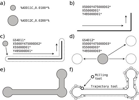
A Flash simply images the currently selected aperture at the given X,Y location. For example:
D100*
X01000Y01500D03*
This selects aperture D100 and flashes it at (100, 150).
A Draw creates a line segment from the current point to the specified X,Y location using the current aperture. For example:
D101*
X01000Y01500D02*
X01800Y01500D01*
X01800Y00700D01*
This selects a rectangular aperture D101, moves to (100,150), and draws two connected segments to (180, 150) then to (180, 70).
An Arc is simply a Draw that also takes I and J offset parameters defining the arc center relative to the starting point. For example:
G75*
D100*
X01000Y01000D02*
G02I01000J0D01*
This selects aperture D100, moves to (100,100), and draws a counterclockwise 180 degree arc centered at an offset of (100,0) relative to the start point, i.e. centered at (200,100) in absolute coordinates. The G02 sets counterclockwise mode, while G01 can be used for clockwise arcs.

Aperture Macros
While standard apertures cover most use cases, some pads or board features may require custom shapes. RS-274D supports defining such shapes using Aperture Macros.
An Aperture Macro definition consists of:
- Macro name
- Macro body containing primitives & variables
- Instantiation (AD command) with specific variable values
For example:
%AMDONUT1*
1,1,$1,$2,0*
1,0,$3,$4,0*%
This defines a macro named DONUT1 that consists of two draw primitives (1,1 and 1,0) with variable parameters $1 through $4.
To instantiate the macro and assign D-code:
%AMDONUT1*1,0.02,0.05,0.01,0.03*%
%ADD123DONUT1*%
This instantiates DONUT1 with values (0.02, 0.05, 0.01, 0.03) and assigns it D-code D123 for subsequent referencing in D01/D03 commands.
Aperture Macros support various primitives like draws, arcs, and outline fills, as well as geometric transformations like rotation. This allows concise definition of fairly complex shapes.
Polarity and Levels
Copper layers on a PCB have a specified polarity that indicates whether the drawn features are additive (think copper traces) or subtractive (think isolation milling). The level parameter further distinguishes between the front/back sides of the board.
Polarity is specified with the %LPD command:
%LPD*%
sets Dark (additive) polarity, while
%LPC*%
sets Clear (subtractive) polarity.
The level parameter is set with the %LMN command, where N is an integer (1=top, 2=bottom):
%LM1*%
Step-and-Repeat
A common PCB manufacturing technique is panelization, where multiple copies of a design are arranged in a grid to be fabricated as a single array panel and later cut apart.
To efficiently represent such arrays, RS-274D supports a step-and-repeat (SR) command to replicate the proceeding data block in a grid with specified X and Y offsets.
For example:
%SRX3Y2I5000J4000*%
(data block)
%SR*%
This specifies a 3×2 step-and-repeat with X increments of 5000 (mils) and Y increments of 4000 (mils). The entire data block will be repeated across the array.
File Structure & Typical Layer Stackup
A complete PCB design in RS-274D format typically consists of several Gerber files, one per layer or function. The common layers include:
- Top/Bottom Copper (.gtl, .gbl)
- Top/Bottom Solder Mask (.gts, .gbs)
- Top/Bottom Silkscreen (.gto, .gbo)
- Board Outline (.gko)
- Drill Data (.drl – separate NC format)
The layer type and side is indicated by a standard file extension. Viewed together, the layers form the complete stackup of the manufactured board.
Each Gerber file (.gbr) consists of:
- Parameter settings (MO, FS, LP, etc.)
- Aperture definitions (%AD)
- Drawing commands (D01, D02, D03)
- M02* (end of file)
The matching aperture file (.apr) containing the D-code shape definitions is typically included alongside the .gbr files in the fabrication data package.
FAQ
What is the difference between RS-274D and RS-274X?
RS-274X (aka Gerber X or Extended Gerber) is a newer revision that includes enhancements like:
- Attributes (TF parameter) for conveying metadata like file function
- Simplified format statements without dropping leading zeros
- Standardized aperture primitives (replacing some macro usage)
However, RS-274X maintains compatibility with most RS-274D features. Many concepts like apertures and polarity remain the same.
Are Gerber files human-readable?
While Gerber RS-274D files are encoded as ASCII text, they are not designed for human readability or hand-editing. The numeric formats are very compact and machine-oriented.
However, a knowledgeable user can still open a Gerber file in a text editor to inspect its contents or make small edits. There are also many free Gerber file viewer programs that render the graphical image represented by the Gerber data.
What is the bounding box of a Gerber file?
RS-274D itself does not have an explicit bounding box parameter. The image extent is implicitly defined by the minimum and maximum coordinate positions across all the draw/flash commands.
Some EDA tools will automatically compute and include a %IPPOS command in the header to indicate the image size. However, this is not universal. The safest approach is to determine the extent from the X/Y coordinate extents.
How are the layers aligned and registered?
A fabrication-ready Gerber data package should have all layers aligned to the same origin and datum. However, there is no explicit inter-layer alignment information within the RS-274D files themselves.
Typically the layer alignment is handled by:
- the CAD software that generated the original Gerber files
- the solder mask and silkscreen layers using the same board outline and fiducials as the copper layers
- the fab house CAM engineer carefully checking layer registration before approving the design for production
What is a Gerber netlist?
While RS-274D does not have an explicit netlist representation, it is sometimes useful to generate a netlist describing the board connectivity from the Gerber data. This is referred to as a Gerber netlist.
Generating a Gerber netlist requires specialized software that can identify and link the connected copper features across the top, bottom, and any inner layers. The resulting netlist can be used for tasks like:
- Electronics rule checks (ERC) on the PCB
- Test point generation
- Reverse-engineering a schematic from a PCB
However, an original schematic netlist is preferable when available, as a Gerber netlist is more prone to errors and ambiguity.
No responses yet