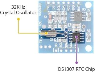
Introduction to the DS1307
The DS1307 is an I2C-based RTC IC that offers a low-power, highly accurate solution for timekeeping. It is widely used in embedded systems, IoT devices, and other applications that require precise time and date information. The DS1307 is capable of keeping track of seconds, minutes, hours, days, months, and years, with automatic leap year compensation.
Key Features of the DS1307
- I2C interface for easy integration
- Low power consumption
- Accurate timekeeping with ±2ppm accuracy
- Automatic leap year compensation
- 56-byte battery-backed SRAM for data storage
- Programmable square-wave output
- Wide operating voltage range (4.5V to 5.5V)
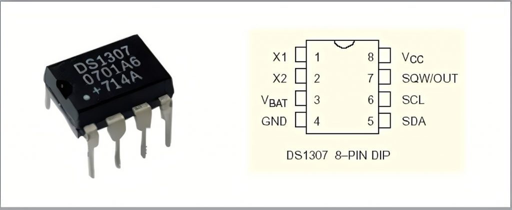
DS1307 Pinout and Pin Description
The DS1307 is available in an 8-pin DIP (Dual Inline Package) or an 8-pin SOIC (Small Outline Integrated Circuit) package. The following table provides a detailed description of each pin:
| Pin Number | Pin Name | Description |
|---|---|---|
| 1 | X1 | 32.768 kHz crystal connection |
| 2 | X2 | 32.768 kHz crystal connection |
| 3 | VBAT | +3V battery input for backup power |
| 4 | GND | Ground |
| 5 | SDA | Serial Data (I2C data line) |
| 6 | SCL | Serial Clock (I2C clock line) |
| 7 | SQW/OUT | Square Wave/Output Driver (programmable) |
| 8 | VCC | +5V power supply |
Crystal Connection (X1 and X2)
The DS1307 requires a 32.768 kHz crystal to be connected between the X1 and X2 pins for accurate timekeeping. The crystal should have a load capacitance of 12.5 pF, which is typically achieved by adding two 12.5 pF capacitors in parallel with the crystal.
Battery Input (VBAT)
The VBAT pin is used to provide backup power to the DS1307 when the main power supply is disconnected. By connecting a 3V lithium battery (such as a CR2032) to this pin, the DS1307 can continue to keep time even in the absence of the main power supply.
I2C Interface (SDA and SCL)
The DS1307 communicates with a microcontroller or other devices using the I2C protocol. The SDA (Serial Data) and SCL (Serial Clock) pins are used for data transfer and synchronization, respectively. The DS1307 operates as a slave device on the I2C bus, with a default 7-bit slave address of 0x68.
Square Wave/Output Driver (SQW/OUT)
The SQW/OUT pin can be programmed to generate a square wave signal with one of four frequencies: 1 Hz, 4.096 kHz, 8.192 kHz, or 32.768 kHz. This feature is useful for generating clock signals or triggering external events. Alternatively, this pin can be used as an output driver for other purposes.
Interfacing the DS1307 with a Microcontroller
To integrate the DS1307 into your project, you’ll need to connect it to a microcontroller that supports the I2C protocol. Most modern microcontrollers, such as Arduino boards or ESP32/ESP8266 modules, have built-in I2C peripherals.
Wiring the DS1307 to an Arduino
Here’s an example of how to wire the DS1307 to an Arduino Uno:
| DS1307 Pin | Arduino Pin |
|---|---|
| VCC | 5V |
| GND | GND |
| SDA | A4 (SDA) |
| SCL | A5 (SCL) |
Remember to connect the 32.768 kHz crystal and capacitors between the X1 and X2 pins, and optionally connect a 3V battery to the VBAT pin for backup power.
Setting up the Arduino IDE
To use the DS1307 with Arduino, you’ll need to install the “RTClib” library in the Arduino IDE. Follow these steps:
- Open the Arduino IDE
- Go to Sketch -> Include Library -> Manage Libraries
- Search for “RTClib” in the search bar
- Select the “RTClib by Adafruit” library and click “Install”
Arduino Code Example
Here’s a simple Arduino sketch that demonstrates how to set and read the time from the DS1307
This code initializes the DS1307, sets the time (if the line is uncommented), and continuously reads and prints the current date and time every second.

Frequently Asked Questions (FAQ)
- Q: Can the DS1307 keep time without a battery?
A: Yes, the DS1307 can keep time as long as it is powered by the main power supply (VCC). However, if the main power is disconnected, a backup battery is required to maintain timekeeping. - Q: What is the accuracy of the DS1307?
A: The DS1307 has an accuracy of ±2 parts per million (ppm), which translates to an error of about 1 minute per year. - Q: Can I use a different crystal frequency with the DS1307?
A: No, the DS1307 is designed to work with a 32.768 kHz crystal. Using a different frequency crystal will result in inaccurate timekeeping. - Q: How do I change the I2C address of the DS1307?
A: The DS1307 has a fixed I2C address of 0x68 and cannot be changed. - Q: Can I use the DS1307 with a 3.3V microcontroller?
A: Yes, the DS1307 is compatible with both 5V and 3.3V microcontrollers. However, you should ensure that the VCC pin of the DS1307 is connected to the appropriate voltage level.
Conclusion
The DS1307 is a reliable and easy-to-use RTC IC that provides accurate timekeeping for a wide range of applications. By understanding the DS1307 pinout and its features, you can easily integrate it into your projects using a microcontroller with I2C support. With its low power consumption, battery backup capability, and programmable square wave output, the DS1307 is an excellent choice for embedded systems, IoT devices, and other projects that require precise time and date information.
No responses yet