Introduction to Circuit Board Components
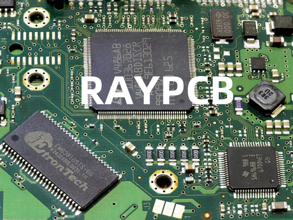
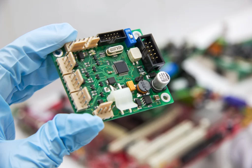
Circuit boards, also known as printed circuit boards (PCBs), are the backbone of modern electronics. They are used in a wide range of devices, from simple gadgets to complex industrial equipment. Understanding the various components that make up a circuit board is essential for anyone involved in electronics design, manufacturing, or repair. In this comprehensive guide, we will explore the key circuit board components and their functions.
Types of Circuit Boards
Before diving into the components, let’s briefly discuss the different types of circuit boards:
- Single-sided PCBs: These boards have components and conductive tracks on one side only.
- Double-sided PCBs: These boards have components and conductive tracks on both sides, connected through drilled holes called vias.
- Multi-layer PCBs: These boards consist of multiple layers of conductive tracks separated by insulating layers, allowing for more complex designs and higher component density.

Essential Circuit Board Components
Resistors
Resistors are passive components that resist the flow of electrical current. They are used to control voltage levels, divide voltages, and limit current in a circuit. Resistors are available in various types, such as carbon film, metal film, and wire-wound, each with its own characteristics and applications.
| Resistor Type | Characteristics | Applications |
|---|---|---|
| Carbon Film | Low cost, low precision, low power | General purpose, low-end electronics |
| Metal Film | Higher precision, higher stability, low noise | Precision circuits, audio equipment |
| Wire-Wound | High power handling, high precision | Power supplies, high-current applications |
Capacitors
Capacitors are passive components that store electrical energy in an electric field. They are used for filtering, decoupling, and smoothing voltage fluctuations in a circuit. Capacitors come in various types, such as ceramic, electrolytic, and tantalum, each with its own properties and applications.
| Capacitor Type | Characteristics | Applications |
|---|---|---|
| Ceramic | Low cost, small size, high frequency response | Decoupling, high-frequency filtering |
| Electrolytic | High capacitance, polarized, larger size | Power supply filtering, low-frequency applications |
| Tantalum | High capacitance, small size, low leakage | Decoupling, high-frequency filtering |
Inductors
Inductors are passive components that store electrical energy in a magnetic field. They are used for filtering, noise suppression, and energy storage in a circuit. Inductors are available in various types, such as air-core, ferrite-core, and iron-core, each with its own characteristics and applications.
| Inductor Type | Characteristics | Applications |
|---|---|---|
| Air-Core | Low inductance, high frequency response | High-frequency circuits, RF applications |
| Ferrite-Core | High inductance, low resistance, high frequency response | EMI suppression, power supply filtering |
| Iron-Core | High inductance, high current handling, low frequency response | Low-frequency filtering, energy storage |
Integrated Circuits (ICs)
Integrated circuits, or ICs, are miniaturized electronic circuits that contain multiple components, such as transistors, diodes, and resistors, on a single chip. ICs are used for a wide range of functions, including amplification, signal processing, data storage, and computation. Some common types of ICs are:
- Microcontrollers: These are programmable ICs that contain a processor, memory, and input/output peripherals, allowing them to control various functions in a device.
- Operational Amplifiers (Op-Amps): These are high-gain amplifiers used for signal conditioning, filtering, and mathematical operations.
- Voltage Regulators: These ICs maintain a constant output voltage despite variations in input voltage or load current, ensuring stable power supply to other components.
Diodes
Diodes are semiconductor devices that allow current to flow in only one direction. They are used for rectification, protection against reverse voltage, and voltage reference in a circuit. Some common types of diodes are:
- Rectifier Diodes: These diodes convert alternating current (AC) to direct current (DC) by allowing current to flow only in one direction.
- Zener Diodes: These diodes are designed to operate in reverse breakdown mode, providing a stable reference voltage for voltage regulation and protection.
- Light-Emitting Diodes (LEDs): These diodes emit light when current flows through them, and are used for indicator lights, displays, and lighting applications.
Transistors
Transistors are semiconductor devices that can amplify or switch electronic signals. They are the building blocks of modern electronics and are used in a wide range of applications, from simple switches to complex amplifiers and digital logic circuits. The two main types of transistors are:
- Bipolar Junction Transistors (BJTs): These transistors are current-controlled devices that can amplify or switch signals based on the current flowing through their base terminal.
- Field-Effect Transistors (FETs): These transistors are voltage-controlled devices that can amplify or switch signals based on the voltage applied to their gate terminal. MOSFETs (Metal-Oxide-Semiconductor FETs) are the most common type of FETs used in modern electronics.
Connectors
Connectors are used to establish electrical and mechanical connections between different parts of a circuit board or between a circuit board and external devices. There are numerous types of connectors, each designed for specific applications and requirements. Some common types of connectors are:
- Pin Headers: These are male connectors with a series of pins that can be soldered to a circuit board and mate with female sockets or jumper wires.
- Screw Terminals: These connectors allow wires to be securely attached to a circuit board using screws, providing a reliable connection for power or signal transmission.
- USB Connectors: These connectors are used for data transfer and power supply between a circuit board and external devices, such as computers or peripherals.

PCB Assembly and Soldering
Once the components are selected and the circuit board is designed, the next step is to assemble the components onto the board. This process involves soldering, which is the act of joining two metal surfaces by melting a filler metal (solder) between them. Soldering can be done manually using a soldering iron or automatically using wave soldering or reflow soldering machines.
Soldering Tips and Best Practices
To ensure reliable and high-quality solder joints, follow these tips and best practices:
- Use the appropriate solder wire for your application, considering factors such as alloy composition, diameter, and flux type.
- Maintain a clean and tinned soldering iron tip to ensure efficient heat transfer and prevent oxidation.
- Apply heat to both the component lead and the PCB pad simultaneously, allowing the solder to melt and flow evenly.
- Avoid applying excessive heat or solder, as this can lead to bridging, overheating of components, or damage to the PCB.
- Inspect solder joints visually and with a multimeter to ensure proper connections and avoid cold solder joints or short circuits.

Testing and Troubleshooting
After assembling the circuit board, it is essential to test its functionality and troubleshoot any issues that may arise. Some common testing and troubleshooting techniques include:
- Visual Inspection: Carefully examine the circuit board for any visible defects, such as solder bridges, cold solder joints, or damaged components.
- Continuity Testing: Use a multimeter to check for continuity between various points on the circuit board, ensuring that connections are properly made and there are no short circuits.
- Power-On Testing: Apply power to the circuit board and verify that it functions as intended, checking for proper voltage levels, signal integrity, and overall performance.
- Oscilloscope Testing: Use an oscilloscope to visualize and analyze signals in the circuit, helping to identify issues such as noise, distortion, or timing problems.
- Functional Testing: Test the circuit board in its intended application, ensuring that it meets the required specifications and performs reliably under various conditions.
Frequently Asked Questions (FAQ)
- What is the difference between through-hole and surface-mount components?
- Through-hole components have leads that are inserted into drilled holes in the PCB and soldered on the opposite side, while surface-mount components are soldered directly onto the surface of the PCB. Surface-mount components are smaller and allow for higher component density, but through-hole components are easier to handle and replace.
- What is the purpose of a decoupling capacitor?
- Decoupling capacitors are used to reduce noise and stabilize the power supply voltage for ICs and other components. They are placed close to the power pins of ICs to provide a local reservoir of charge and filter out high-frequency noise.
- How do I identify the value of a resistor or capacitor?
- Resistors and capacitors are often marked with color codes or numerical codes that indicate their value and tolerance. You can use a resistor color code chart or a capacitor code calculator to determine the value based on the markings on the component.
- What is the difference between a linear voltage regulator and a switching voltage regulator?
- Linear voltage regulators reduce the input voltage to a lower, stable output voltage by dissipating the excess energy as heat. They are simple and low-noise but have lower efficiency. Switching voltage regulators, on the other hand, use a high-frequency switching technique to regulate the output voltage, resulting in higher efficiency but more complexity and potential noise.
- How can I prevent electrostatic discharge (ESD) damage when handling circuit boards and components?
- To prevent ESD damage, always handle circuit boards and components in an ESD-safe environment, using grounded wrist straps, ESD mats, and antistatic bags. Avoid touching components directly, and always discharge any static buildup before handling sensitive components.
Conclusion
Understanding circuit board components and their functions is crucial for anyone involved in electronics design, manufacturing, or repair. By familiarizing yourself with the various types of components, their characteristics, and their applications, you can design more effective and reliable electronic devices. Additionally, proper soldering techniques, testing, and troubleshooting skills are essential for ensuring the quality and performance of your circuit boards.
As technology continues to advance, new components and techniques will emerge, making it important to stay up-to-date with the latest developments in the field. By continually learning and expanding your knowledge of circuit board components, you can stay at the forefront of the electronics industry and create innovative solutions to meet the ever-growing demands of the modern world.

No responses yet