PCB Design Environment
At the core of Altium is its powerful PCB design environment. It provides an intuitive interface for creating schematics, layouts, and manufacturing files.
Schematic Capture
Altium’s schematic editor allows you to quickly enter designs using an extensive library of pre-built components. Key features include:
- Multi-sheet designs
- Automated wire numbering
- Real-time design rule checking
- Export to simulation tools
PCB Layout
The PCB layout environment is where you’ll spend most of your time in Altium. It provides advanced routing and placement tools:
| Feature | Description |
|---|---|
| Interactive Routing | Quickly route traces with the help of visual guides and real-time design rule checking |
| Differential Pair Routing | Easily route high-speed differential pairs while controlling impedance |
| 3D Modeling | View your board as a realistic 3D model and check mechanical fit |
| Rigid-Flex Design | Create rigid-flex PCB designs with specialized stack-up and bend area tools |
Manufacturing Outputs
When your design is complete, Altium can generate all the manufacturing files you need:
- Gerber files
- NC drill files
- Pick and place files
- 3D files (STEP, IGES)
- BOM
Library Management
Altium includes a robust library management system for organizing components, footprints, symbols, and other design data.
Content Vaults
Content Vaults provide secure storage and version control for your design data. You can:
- Check items in and out
- View revision history
- Share libraries between teams
Access to Supplier Data
Altium provides access to an extensive online library of supplier components and data, allowing you to:
- Search for components by parametric data
- Access up-to-date pricing and availability info
- Download symbols, footprints, and 3D models
Project Management
Altium has several tools to help manage the overall design process for your electronics projects.
Version Control
Altium integrates with popular version control systems like Git and SVN. This allows you to:
- Collaborate with team members
- Manage design revisions
- Resolve conflicts
Release Management
Altium’s release management tools help you prepare designs for production:
- Generate complete manufacturing output packages
- Compare differences between versions
- Track approval status

Simulation
Altium includes several tools for simulating your designs prior to manufacturing.
Mixed-Signal Circuit Simulation
The mixed-signal simulator can verify the functional behavior of your circuits, including:
- Analog/digital components
- Microcontrollers
- Embedded software
Signal Integrity Analysis
Altium can help analyze and resolve signal integrity issues in high-speed designs:
- Impedance calculation
- Termination analysis
- Reflection analysis
Power Integrity Analysis
The power integrity tools allow you to optimize your PDN (power distribution network):
- DC voltage drop
- Decoupling capacitor placement
- Power plane shapes

Mechanical Integration
Altium helps bridge the gap between electrical and mechanical design.
MCAD Collaboration
You can collaborate with mechanical designers by:
- Importing PCB data into MCAD tools (Solidworks, etc.)
- Defining the board shape in the MCAD tool
- Updating the PCB with mechanical changes
3D Clearance Checking
Altium can check 3D clearances between the PCB and mechanical enclosure to verify fit and resolve collisions.
Frequently Asked Questions
What types of designs is Altium best suited for?
Altium is a versatile tool suited for a wide range of electronics, including consumer products, aerospace systems, medical devices, and telecommunications equipment. Its advanced features make it especially well-suited for high-speed digital, analog/mixed-signal, and rigid-flex designs.
How does Altium compare to other PCB design tools?
Altium is known for its modern user interface, ease of use, and powerful feature set. It competes with other professional tools like Cadence Allegro and Mentor Graphics PADS. Compared to mid-range tools like Eagle or KiCAD, Altium offers more advanced features and can handle larger, more complex designs.
What kind of support and training is available for Altium?
Altium offers several support and training options:
- Online documentation
- Built-in tutorials
- Instructor-led training classes
- Forums and user communities
- Paid support plans
Can Altium import designs from other tools?
Yes, Altium can import designs from most other PCB Tools via standard file formats:
- ODB++
- IPC-2581
- PADS ASCII
- Eagle XML
It can also import schematics via the DXF or EDIF formats.
What are the system requirements for Altium?
The current minimum system requirements for Altium Designer 22 are:
- 64-bit Windows 10
- Intel or AMD processor, 2GHz or faster
- 16 GB RAM
- 5 GB free disk space
- 1920×1080 or higher display resolution
Conclusion
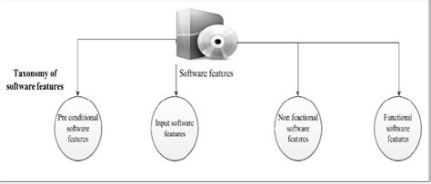
In this guide, we’ve covered the key Software Features that make Altium a powerful and versatile tool for electronics design. From its core PCB design environment, to its library management, project management, simulation, and mechanical integration capabilities, Altium provides a comprehensive set of tools to help bring your electronics products to market quickly and efficiently.
Whether you’re a seasoned engineer or just starting out, Altium’s intuitive interface and extensive resources make it accessible to a wide range of users. Its advanced features and customization options allow it to scale up to the most demanding professional design needs.
While we’ve touched on many of the most important features here, the best way to really appreciate Altium’s capabilities is to try it out yourself. With its fully-functional free trial, you can explore all that Altium has to offer and see how it can boost your productivity and streamline your design process. So why not download it today and start designing the future of electronics?
No responses yet