Introduction to PCB Visualizer Tools
PCB visualizer tools allow engineers and designers to view, analyze, and optimize printed circuit board (PCB) designs. These software tools provide a graphical representation of the PCB layout, enabling users to inspect various aspects such as component placement, routing, drill holes, slots, and more. By leveraging PCB visualizers, professionals can identify potential issues early in the design process, ensure manufacturability, and enhance the overall quality of their PCB designs.
In this article, we will explore the Drill & Slot editor, a free and powerful PCB visualizer tool that offers a range of features to streamline the PCB design workflow. We will delve into the key features of the Drill & Slot editor, provide step-by-step instructions on how to use its various functionalities, and share valuable tips and tricks to help you make the most of this tool.
Key Features of the Drill & Slot Editor PCB Visualizer
The Drill & Slot editor PCB visualizer comes packed with a comprehensive set of features designed to assist PCB designers and engineers. Some of the notable features include:
-
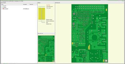
Intuitive User Interface: The Drill & Slot editor offers a user-friendly interface that makes navigation and interaction with the PCB design seamless and efficient.
-
2D and 3D Visualization: Users can view their PCB designs in both 2D and 3D modes, enabling them to analyze the layout from different perspectives and identify potential issues.
-
Drill Hole and Slot Editing: The tool provides powerful editing capabilities for drill holes and slots, allowing users to modify their size, shape, and placement with ease.
-
Layer Management: The Drill & Slot editor supports multiple layers, enabling users to organize and manage different aspects of their PCB design effectively.
-
Design Rule Checking (DRC): The integrated DRC feature helps users identify and resolve design rule violations, ensuring that the PCB layout adheres to the specified manufacturing constraints.
-
Measurement Tools: The visualizer includes a range of measurement tools that allow users to accurately determine distances, angles, and dimensions within the PCB design.
-
Export Options: Users can export their PCB designs in various file formats, facilitating seamless collaboration with other tools and manufacturing processes.

Getting Started with the Drill & Slot Editor
To begin using the Drill & Slot editor PCB visualizer, follow these steps:
- Download and install the Drill & Slot editor software on your computer.
- Launch the application and create a new project or open an existing PCB design file.
- Familiarize yourself with the user interface and the available tools and options.
- Import your PCB design files, such as Gerber files or ODB++ files, into the Drill & Slot editor.
- Organize and assign the imported files to the appropriate layers within the visualizer.
- Customize the display settings, such as color schemes and layer visibility, to suit your preferences.

Navigating the 2D and 3D Views
The Drill & Slot editor provides both 2D and 3D views of your PCB design, allowing you to analyze the layout from different perspectives. Here’s how you can navigate these views effectively:
2D View Navigation
- Use the mouse wheel or zoom controls to zoom in and out of the PCB layout.
- Click and drag the mouse to pan around the design.
- Right-click on any component or element to access context-specific options and properties.
- Use keyboard shortcuts to quickly access common functions (e.g., “Ctrl + Z” for undo, “Ctrl + S” for save).
3D View Navigation
- Rotate the 3D view by clicking and dragging the mouse while holding the right mouse button.
- Zoom in and out using the mouse wheel or dedicated zoom controls.
- Pan the view by clicking and dragging the mouse while holding the middle mouse button or using the designated pan tool.
- Adjust the camera settings, such as field of view and perspective, to optimize the 3D representation.

Editing Drill Holes and Slots
One of the core features of the Drill & Slot editor is its ability to edit drill holes and slots within the PCB design. Follow these steps to modify drill holes and slots:
- Select the drill hole or slot you want to edit by clicking on it in the 2D or 3D view.
- Use the properties panel or context menu to access the editing options for the selected element.
- Modify the size, shape, or position of the drill hole or slot using the available tools and settings.
- Apply the changes and review the updated design to ensure the modifications meet your requirements.
Here are some tips for editing drill holes and slots effectively:
- Use the snap-to-grid feature to align drill holes and slots precisely.
- Leverage the copy and paste functionality to duplicate drill holes or slots and maintain consistency.
- Utilize the undo and redo commands to easily revert or restore changes made to drill holes and slots.
Managing Layers in the PCB Design
The Drill & Slot editor supports multiple layers, allowing you to organize and manage different aspects of your PCB design. Here’s how you can work with layers effectively:
- Access the layer management panel or use keyboard shortcuts to toggle between layers.
- Create new layers or import existing layers from your design files.
- Assign specific elements, such as components, traces, or drill holes, to the appropriate layers.
- Customize the visibility and color settings for each layer to enhance visual clarity and organization.
- Use layer groups to organize related layers and simplify layer management.
Consider the following tips when managing layers in your PCB design:
- Establish a consistent naming convention for layers to maintain clarity and avoid confusion.
- Utilize layer visibility settings to focus on specific aspects of the design while hiding unnecessary information.
- Employ layer groups to quickly enable or disable multiple layers simultaneously.
Performing Design Rule Checks (DRC)
The Drill & Slot editor includes a built-in Design Rule Check (DRC) feature that helps identify and resolve design rule violations. Follow these steps to perform a DRC:
- Access the DRC settings or commands within the Drill & Slot editor.
- Configure the DRC rules and constraints based on your PCB manufacturing requirements.
- Run the DRC process to analyze the PCB layout for potential violations.
- Review the DRC results, which typically include a list of violations and their locations within the design.
- Address each violation by making necessary modifications to the PCB layout.
- Rerun the DRC to ensure all violations have been resolved.
Here are some tips for effective DRC usage:
- Regularly perform DRCs throughout the design process to catch and rectify issues early on.
- Customize DRC rules and constraints to match the specific requirements of your PCB manufacturer.
- Prioritize and address critical DRC violations first to ensure the manufacturability of your design.
Using Measurement Tools
The Drill & Slot editor provides various measurement tools to accurately determine distances, angles, and dimensions within your PCB design. Here’s how you can utilize these tools:
- Select the appropriate measurement tool from the toolbar or menu.
- Click on the starting point and endpoint of the measurement you want to take.
- The measurement result will be displayed, typically in the status bar or a dedicated measurement panel.
- Use the available options to customize the measurement units, precision, and display format.
Consider these tips when using measurement tools:
- Use keyboard shortcuts or toolbar buttons to quickly access measurement tools.
- Take advantage of snap-to-grid or object snapping to ensure precise measurements.
- Utilize the measurement data to verify component placement, trace widths, and clearances.
Exporting PCB Designs
Once you have finalized your PCB design using the Drill & Slot editor, you can export it in various file formats for manufacturing or collaboration purposes. Follow these steps to export your PCB design:
- Access the export options or commands within the Drill & Slot editor.
- Select the desired file format for export, such as Gerber, ODB++, or IPC-2581.
- Configure the export settings, including layer selection, file naming conventions, and output directory.
- Initiate the export process and wait for the files to be generated.
- Verify the exported files to ensure they contain the necessary information and are correctly formatted.
Here are some tips for successful PCB design export:
- Choose the appropriate file format based on your manufacturing partner’s requirements.
- Include all necessary layers and files in the export, such as drill files and solder mask layers.
- Use clear and descriptive file naming conventions to facilitate easy identification and communication.
Frequently Asked Questions (FAQ)
-
Is the Drill & Slot editor compatible with both Windows and macOS?
Yes, the Drill & Slot editor is available for both Windows and macOS operating systems. You can download the appropriate version from the official website. -
Can I import PCB designs created in other software tools into the Drill & Slot editor?
Yes, the Drill & Slot editor supports importing PCB design files from various popular PCB design software tools. It accepts file formats such as Gerber, ODB++, and IPC-2581. -
Is there a limit to the number of layers I can have in my PCB design?
The Drill & Slot editor does not impose a specific limit on the number of layers. However, the practical limit may depend on the complexity of your design and the performance of your computer. -
Can I customize the keyboard shortcuts in the Drill & Slot editor?
Yes, the Drill & Slot editor allows you to customize keyboard shortcuts according to your preferences. You can access the keyboard shortcut settings from the application’s preferences or options menu. -
How can I get support or report a bug in the Drill & Slot editor?
If you encounter any issues or have questions regarding the Drill & Slot editor, you can visit the official support forum or contact the software vendor’s customer support team. They will be able to provide assistance and guidance specific to your needs.
Conclusion
The Drill & Slot editor is a powerful and free PCB visualizer tool that offers a wide range of features to streamline the PCB design process. By leveraging its intuitive interface, 2D and 3D visualization capabilities, drill hole and slot editing tools, layer management, DRC functionality, and measurement tools, PCB designers and engineers can efficiently analyze, optimize, and finalize their PCB layouts.
By following the tips and tricks outlined in this article, you can make the most of the Drill & Slot editor and enhance your PCB design workflow. Remember to regularly perform design rule checks, utilize the available navigation and editing tools, and export your designs in the appropriate file formats for seamless collaboration and manufacturing.
With its comprehensive feature set and user-friendly interface, the Drill & Slot editor PCB visualizer is a valuable asset for any PCB design professional seeking to create high-quality and manufacturable PCB layouts.
| Feature | Description |
|---|---|
| Intuitive User Interface | User-friendly interface for seamless navigation and interaction |
| 2D and 3D Visualization | View PCB designs in both 2D and 3D modes for comprehensive analysis |
| Drill Hole and Slot Editing | Modify size, shape, and placement of drill holes and slots |
| Layer Management | Organize and manage multiple layers for effective PCB design |
| Design Rule Checking | Identify and resolve design rule violations for manufacturability |
| Measurement Tools | Accurately determine distances, angles, and dimensions within the design |
| Export Options | Export PCB designs in various file formats for collaboration and manufacturing |
No responses yet